

I have been trying to build an amplifier. I don't want to design one (I am not an electronics or
audio engineer), and so I looked on line for good choices. Not a lot available! At least not
much I could find that would sound decent and not require more technical knowledge than I have
(or was willing to learn). After trying a relatively cheap kit that I found on Amazon,
which I never got to work, I found designs by
Elliot Sound Products based in Australia. I looked through the site, then I looked for
reviews online--there appear to be many happy amplifier builders who use his designs! So I
ordered the Printed Circuit Board (PCB) for the P3A (rev3) Amplifier. This is an image of the
board that I received (click images for full-sized views):
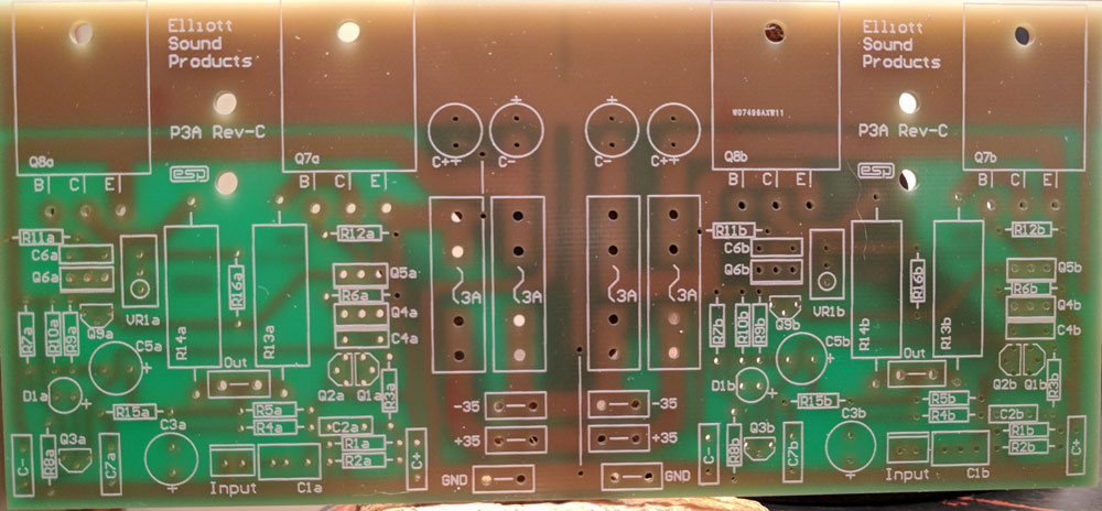
Some information about the amp. It is a
Class AB Stereo amplifier
capable of up to 100 Watts per channel, depending on the power supply. I think mine will top out at around 60W
per channel, but more on that later. Here are the specs
from the Elliot Sound Products site:
| Gain | 27dB |
| Input Impedance | 24k |
| Input Sensitivity | 1.22V for 100W (8 ohms) |
| Frequency response 1 | 10Hz to 30kHz (-1dB) typical |
| Distortion (THD) | 0.04% typical at 1W to 80W |
| Power (42V supplies, 8 ohm load) 2 | 90W |
| Power (35V supplies, 8 ohm load) 3 | 60W |
| Power (35V supplies, 4 ohm load) | 100W |
| Hum and Noise 4 | -73 dBV unweighted |
| DC Offset | < 100mV |
|
1. The frequency response is dependent on the value for the input and feedback
capacitors, and the above is typical of that when the specified values are used.
The high frequency response is fixed by C4, and this should not be changed.
| |
|
2. Operation into 4 ohm loads is not recommended with the 42V supplies. Peak
dissipation will exceed 110W in each output transistor, leaving no safety margin
with typical inductive loads. All supply voltages are nominal, at no load - your
transformer may not be capable of maintaining regulation, so power may be
slightly less than shown.
| |
|
3. This figure is typical, and is dependent on the regulation of the power supply
(as are 1 and 2, above). Worst case power with 8 ohm loads is about 50W, but the
supply will be seriously inadequate if the power falls that far.
| |
|
4. This is an extremely pessimistic test, because the bandwidth extends well above and below anything that is audible. The
response of my meter extends from around 3Hz to well over 100kHz, so the measured
noise is much greater than would be the case with any weighting network.
|
|
After receiving the board, I gained access to Rod Elliot's instructions for assembly, along with
general amplifier design and creation information. More than I expected! This info included
a bill of materials, so I started ordering the components. The first items to arrive were the
fuses and fuse clips:
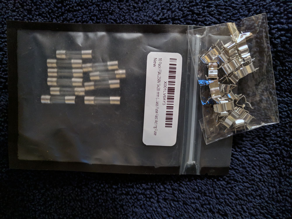
Not too exciting, I know. But I did get to check the fit, to make sure I got the right parts.
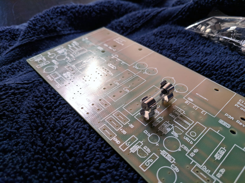
(I had a hard time figuring out if the fuse clips were correct from information online). I
checked, and the clips and fuses fit! Here is proof:
I received all of the parts within a week or so. The capacitors, most of the resistors and some of the transistors came from Mouser Electronics and the rest of the transistors came from Digikey. The fuses, clips and the 5W resistors were ordered through Amazon. (You don't need me to link to Amazon, do you?) I messed up and ordered a few too many of the 5W resistors. I needed 4 and thought I ordered 4. I ordered 4 bags of 15 each. Oops. Luckily one of the bags was delayed so I was able to cancel that one. So I only got 45 instead of 4!
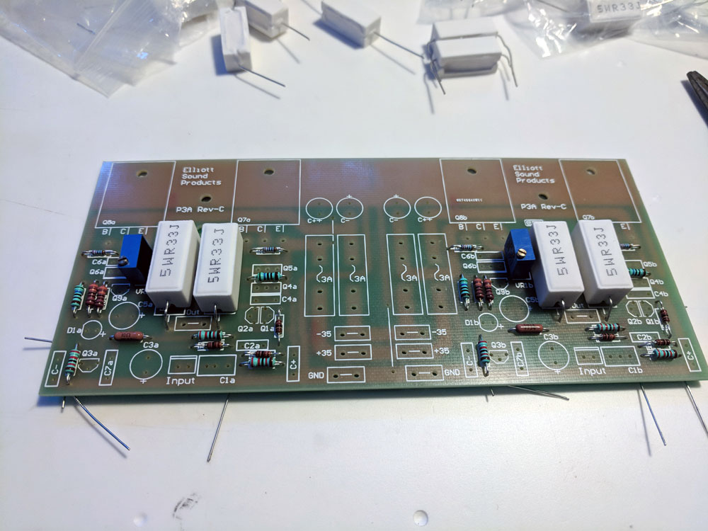
First step--put in the resistors (nothing soldered yet). I test each one before putting it in the board.
Since I had way too many 5W resistors, I used a few to test different fits. I am a bit concerned about
the wattage rating of some of my reistors; a few were specified as either 1/2 Watt or 5 Watts. But the
rest had no power rating. Some of the ones I used were rated for 1/3 of a Watt, while some were 0.4 Watts
. Hope that's enough! They look smaller than those I have seen in pictures of other P3A builds.
Update:
In his description of the amplifier, Rod Elliot says: All resistors should be 1/4W or 1/2W 1%
metal film for lowest noise, with the exception of R9, R10 and R15 which should be 1/2W types,
and R13, R14 must be 5W wirewound.
So I think I'm OK, because 1/3W was the lowest rating any of the resistors I used--higher than 1/4W.
Here's the board with all of the resistors on it (and some of the 5W resistors lying around in the back):
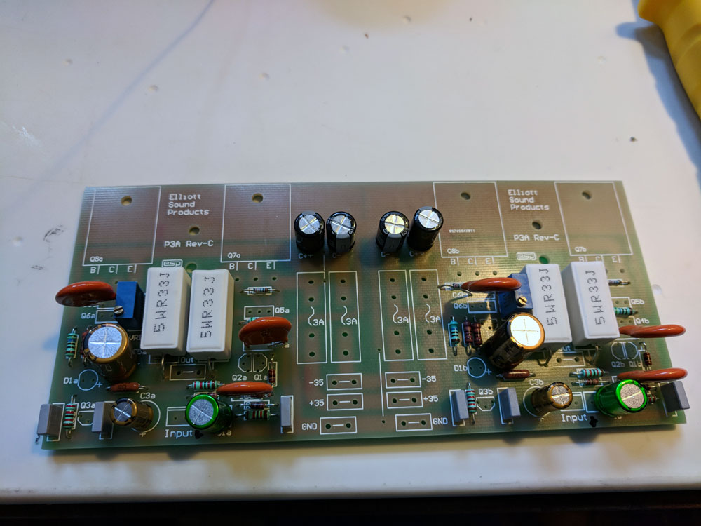
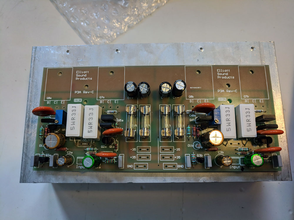
I soldered the resistors, then placed the capacitors. My concern with the capacitors is also about rating and
size. The ceramic capacitors (the beige discs in the photo) are larger than those in the assembly instructions.
They have the correct capacitance, but are rated for 1K Volts (!). I suspect the "proper" ones are rated for
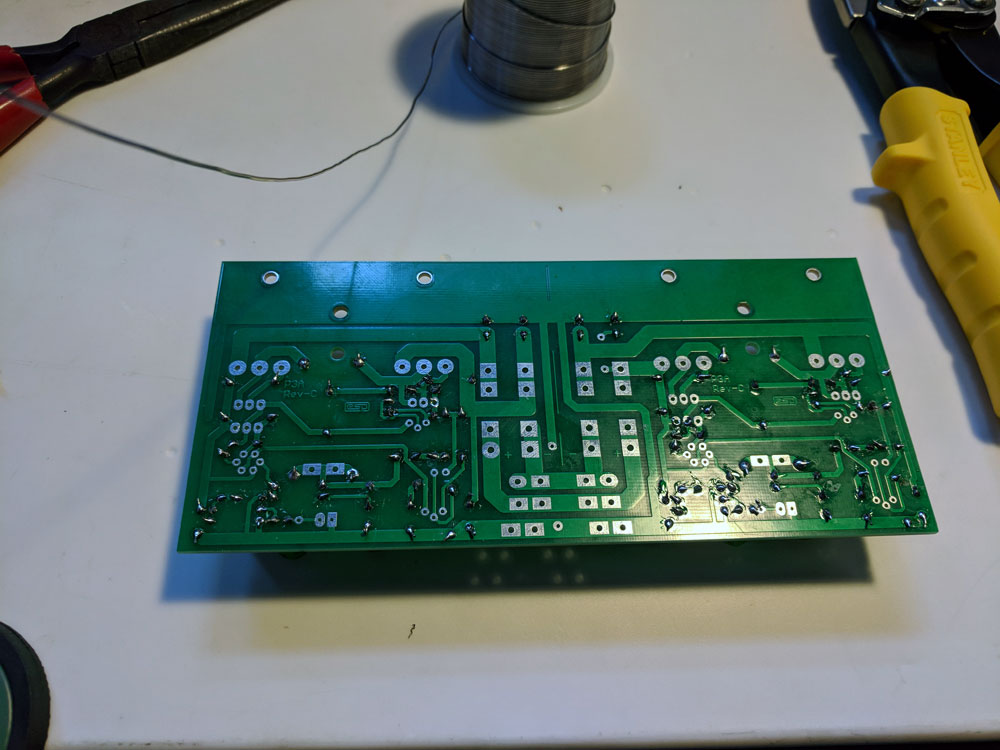
something much smaller like 50V or so. I think that is OK. I hope so. Anyway, the bottom of the board, with
the resistors and capacitors soldered, is in the next picture (don't judge my soldering skills, please), and the
photo afer that shows the top of the board with the R's and C's visible:
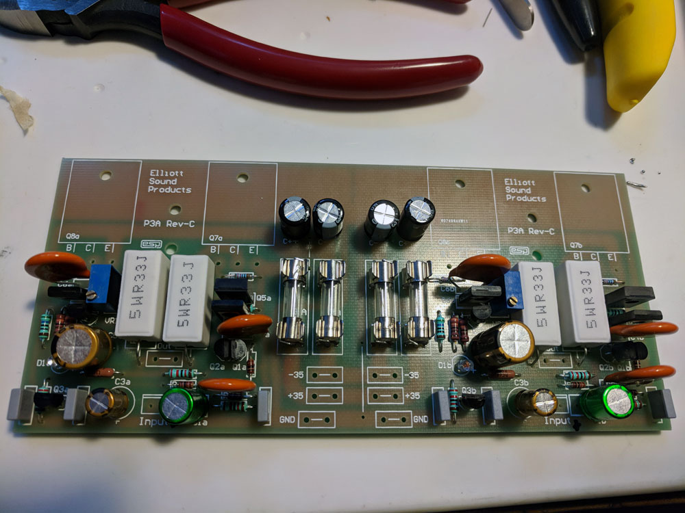
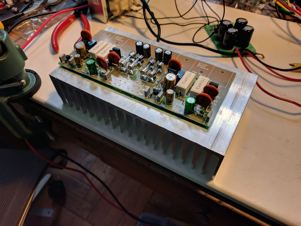
The next step was to add the semiconductors--the transistors and green LED's. And the fuse clips and fuses
(finally!). I did that, except for the big output transistors. They need to be mounted to a heat sink as they
are the components that will get hot. Anyway, this is what the board looks like now:
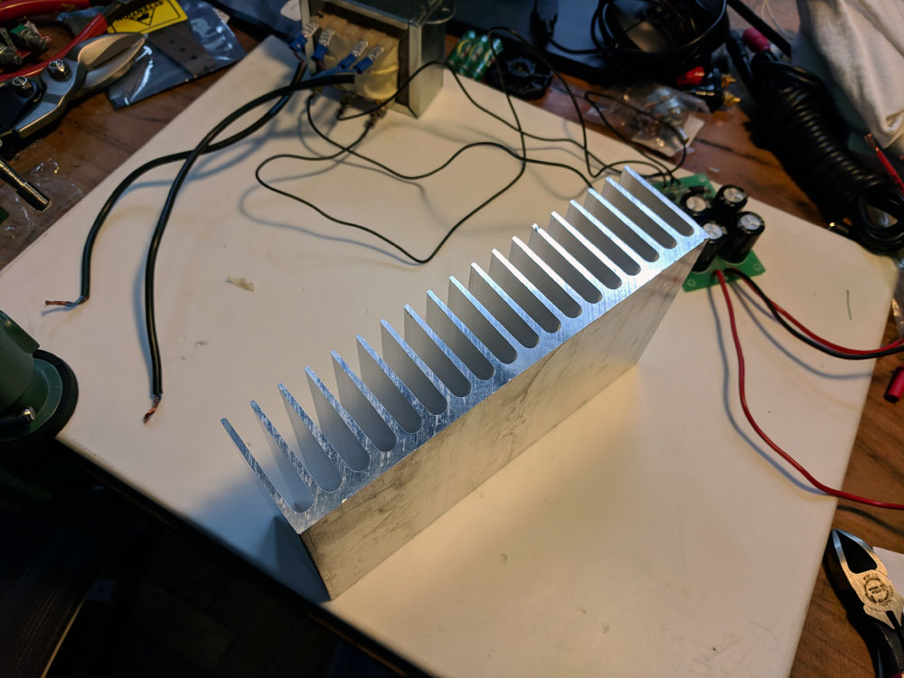
Oh, yeah. I didn't think about a heat sink...so I ordered one based on its size from Amazon. I think it might
be a bit more than needed. (Can't have too much heat sink, according to Rod Elliot.) A picture of the heat
sink on its side, and one with the amp on top of the heat sink:
So now I decided to check on the power supply that I have been saving--I salvaged it from a mini stereo system
I used to own. I was sure that it was +/-35 volts. It is actually +/- 45 Volts--and Rod Elliot
(Elliot Sound Products is his site) advises that 42V is the
absolute maximum and 35 is better. Here is the power supply:
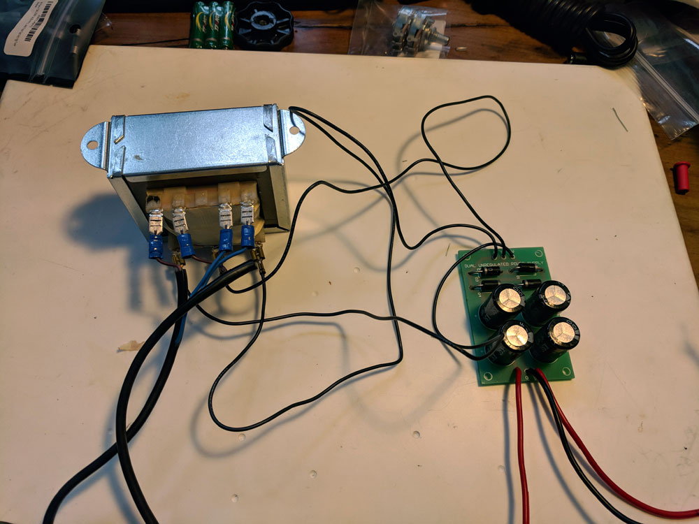
The AC output of the laminated core transformer on the left is rectified and smoothed by the power supply on the
right producing two "rails," plus and minus, of DC voltage. Since the voltage was too high, I spent some time
researching what I could do. I decided to build a buck
converter. So I ordered more parts. My original concern is that I am using a laminated core transformer
(audiophiles prefer torroidal transformers). Now,
added to that concern, I am worried that I am also effectively turning the power supply into a
switching power supply. Another
audiophile sin! We'll see. I can always replace the power supply later.
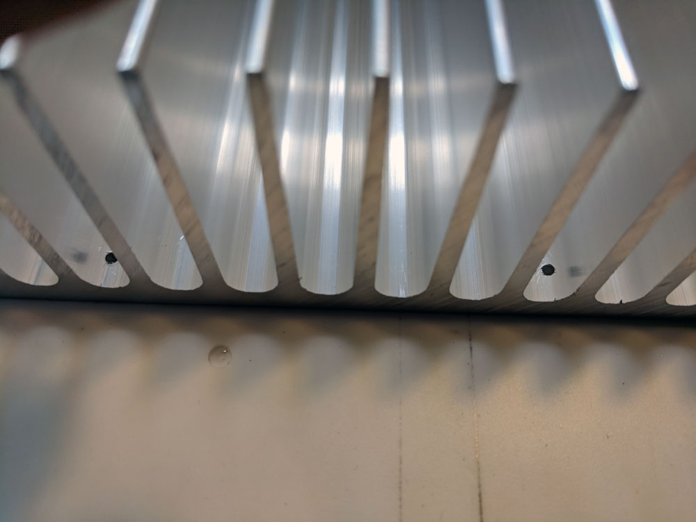
I started working with the heatsink. Firs step is to drill the holes for the bolts that will hold the transistors
and the PCB to the heatsink. The problem is there is no way to line it up right. No matter what I do, at least
some of the holes end up too close to a fin--so I won't be able to put the nut on the bolt. I drilled some pilot
holes, just to make sure, and...bummer! So I now plan to cut into the fins around the holes and grind the area
down to make it as flat as I can. Here are the pilot holes from both sides of the heatsink. You can see the problem
in the second photo:
This is not a pipe. Don't trust me. This is the about page.